 NIUMAG
Samples during magnetic resonance imaging (MRI) experiments, the first question to consider is to determine the direction of three related imaging: selected layer direction (G Slice I), phase encoding direction (G Phase I) and the frequency-encoding direction (G Read I)
In Fig 1, we can see relationship between orthogonal coordinates and the direction of the magnetic field. In the coordinates, Z direction is defined as up and down according to the NMR instrumentation. Y direction is defined as front and back. X direction is defined as left and right. Usually, we make the NMR imaging directions coincide the orthogonal coordinates, i.e. we use X/Y/Z to be slice/phase/read direction. However, we can also make the imaging direction not coincide the orthogonal coordinates. For example, we can choose Z as the slice direction, Y as the phase direction and X as the read direction.
In NMR imaging software, we have three sets of parameters for setting the imaging directions. They are sagittal ,coronal and axial directions.
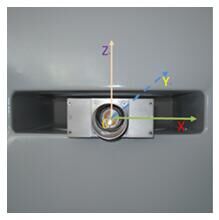
Fig 1 the main direction of magnetic field
1. Sagittal Imaging
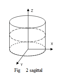
Select the sagittal imaging .As shown in Fig 2.
| G Slice | G Phase | G Read | |
| X | 0 | 0 | 1 |
| Y | 0 | 1 | 0 |
| Z | 1 | 0 | 0 |
We choose Z as the slice direction, Y as the phase direction and X as the read direction, and the image we get will be a sagittal image of the sample. The following is a selection value for each parameter of a sagittal image.
2. Coronal Imaging
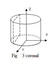
Select the coronal imaging .As shown in Fig 3, we choose X as the slice direction, Z as the phase direction and Y as the read direction, and the image we get will be a coronal image of the sample. The following is a selection value for each parameter of a coronal image.
| G Slice | G Phase | G Read | |
| X | 1 | 0 |
0 |
| Y | 0 | 1 | 0 |
| Z | 0 | 0 | 1 |
3. Transverse Imaging
|
|
G Slice | G Phase | G Read |
| X | 0 | 0 | 1 |
| Y | 1 | 0 | 0 |
| Z | 0 | 1 | 0 |
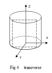
Select the transverse imaging .As shown in Fig 4, we choose Y as the slice direction, Z as the phase direction and X as the read direction and the image we gets will be a transverse image of the sample. The following is a selection value for each parameter of a transverse image.